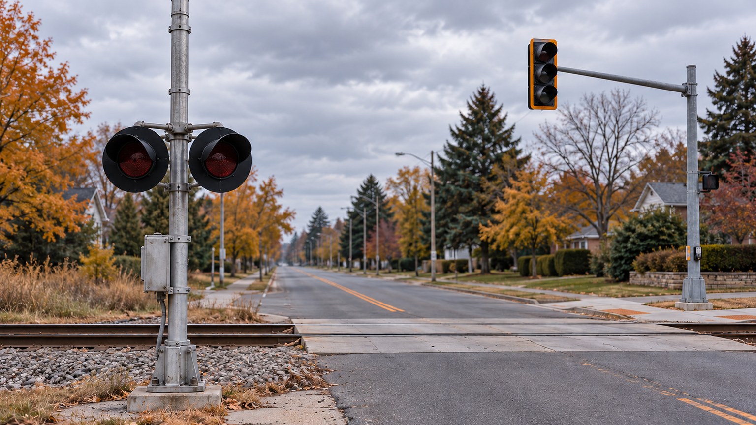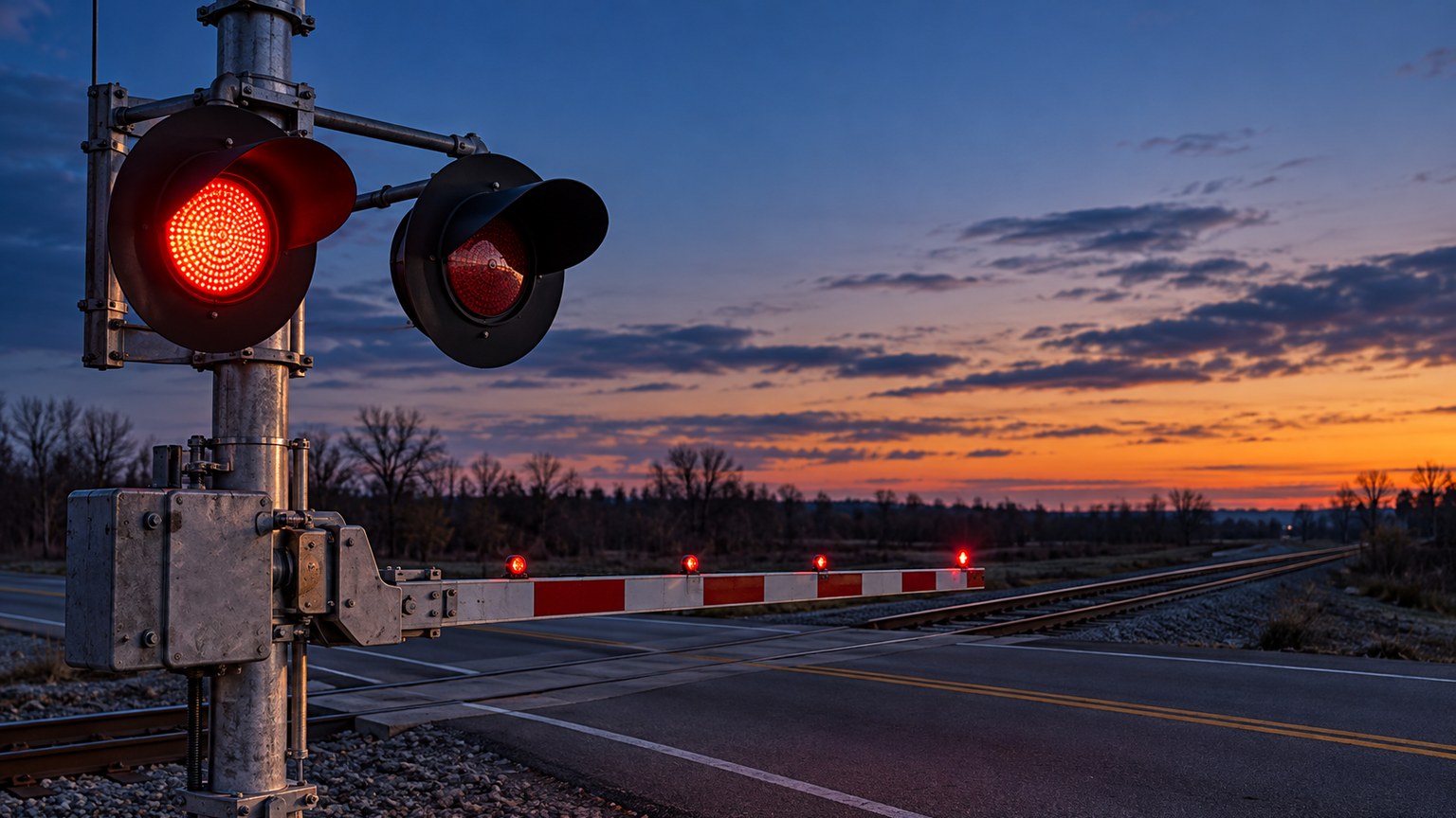

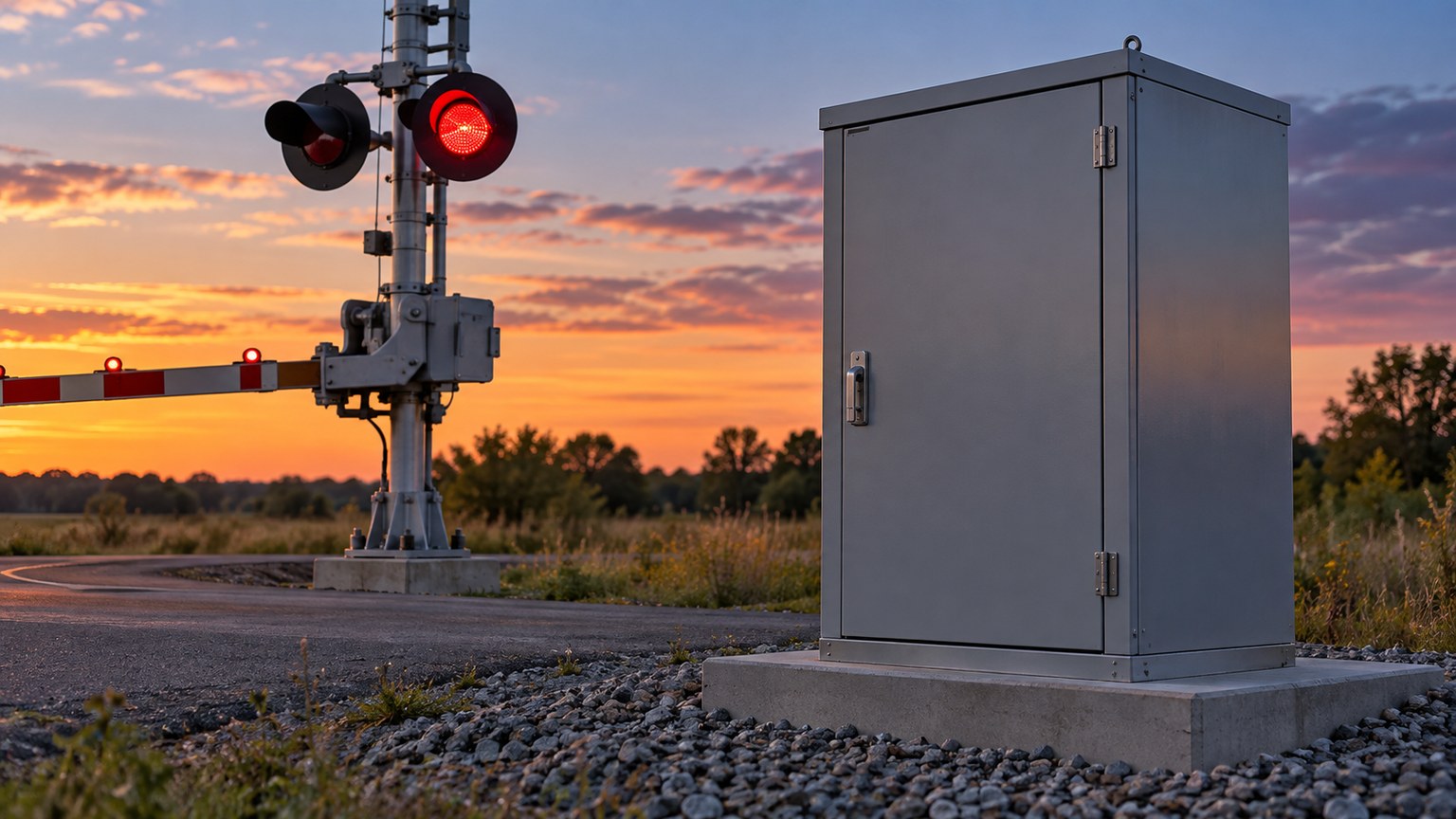
Railroad crossing standby power is a warning-system design question, not a battery-life claim printed on an LED light carton. Crossing lights are normally dark until a train approaches or occupies the crossing. The FRA/FHWA Highway-Rail Crossing Handbook explains why a loss of primary power is not obvious to a road user and why control systems include standby battery power. The exact backup requirement and equipment configuration belong to the responsible railroad’s crossing design.
For a buyer considering an LED light replacement, the useful question is: how will the exact unit’s documented load fit the approved system, including its reserve source and field tests? This article is a documentation and review guide for U.S. active warning systems. It is not a battery-sizing calculation or an instruction to modify a live crossing.
Start with the crossing plan, not a guessed number of hours
49 CFR § 234.215 requires a standby source with sufficient capacity to operate the warning system for a reasonable time during interruption of primary power. The designated capacity is to be specified on the plans required by § 234.201. The regulation does not give a universal “X hours” figure for every crossing in this provision. The project team needs the actual approved plan and its design assumptions.
The handbook describes standby battery arrangements and notes that solar energy can charge storage batteries in remote locations. That background does not make any particular LED lamp “solar ready,” nor does it establish how long a site will run when utility power is lost. Treat any runtime estimate as a system engineering result tied to the site, battery condition, loading, operating profile, and test method.
The warning lights are only part of the load
A light-unit data sheet can contribute one piece of the electrical picture. Depending on the approved crossing architecture, the power review also needs the detection and control equipment, all relevant warning-light units, gate equipment, audible devices, associated electronics, and the charging and distribution arrangement. Not every crossing has every device; use the actual wiring and equipment schedule.
| Document or field | Why the reviewer needs it | Who supplies or confirms it |
|---|---|---|
| Current crossing plan and designated standby capacity | Defines the approved system boundary, equipment and capacity recorded for the site | Railroad signal engineering and current site plans |
| Exact light-unit ordering code and electrical data | Identifies input range, current or power and any behavior relevant to the circuit | Light manufacturer, controlled specification and installation instructions |
| Other installed loads and operating sequence | Captures what the source must support when the warning system is active or idle | Railroad equipment schedule and circuit design |
| Standby source, charger and condition | Connects nominal capacity to the approved design and actual maintenance state | Railroad maintenance records and equipment documentation |
| Verification and record | Shows the required standby and overall system tests were completed after a change | Qualified railroad personnel under their procedures |
This is a handoff map, not a complete electrical design template. The applicable engineering review may require additional components, temperature allowances, battery aging assumptions, wiring losses, and operating conditions.
What an LED replacement can and cannot establish
LED assemblies often use less current than legacy incandescent units in comparable applications, as the FRA/FHWA handbook discusses. But a generic LED-versus-incandescent statement cannot quantify this crossing’s reserve time. A lower load at one light does not prove an approved system modification, a longer guaranteed outage duration, or adequate optical performance. The proposed exact ordering code must meet the railroad’s electrical, optical, mechanical, and acceptance criteria.
Frontier’s public Low Power and High Power 433 pages both list 12Vac/Vdc input, a 12-inch tinted lens, and an integrated sidelight. They do not publish the model-level current and power data needed for a site load calculation in the pages reviewed September 2026. “Low Power” is a family designation, not a battery autonomy specification. Our Low Power versus High Power comparison explains the remaining selection documents to request.
Ask the manufacturer for the controlled electrical data for each proposed exact model and configuration, including the sidelight if applicable. Then have the responsible railroad evaluate it against the current crossing plan, installed power source and charging arrangement. A nominal voltage match alone does not establish an approved substitute.
Build testing and records into the change
49 CFR § 234.251 requires standby power to be tested at least once each month. § 234.257 requires a warning-system operation test when placed in service, at least monthly thereafter, and whenever modified or disarranged. A new light assembly should be reviewed within the railroad’s applicable testing and approval workflow, not simply energized and considered finished.
§ 234.273 addresses the records of required inspections and tests, including the crossing identification, equipment tested, results and any repairs or replacements. For a reported failure rather than a planned replacement, the separate malfunction response guide explains the initial investigation and protection handoff. For budgeting and sourcing at program scale, see the rail-crossing procurement guide.
Frequently asked questions
How many hours must a crossing’s standby battery last?
Section 234.215 calls for sufficient capacity for a reasonable period and requires the designated capacity on the crossing plans. Do not use a universal runtime claim in place of the approved site design.
Will a Low Power light double backup time?
No such ratio follows from the family name. The public product pages do not provide the model-level load figures for that calculation, and the crossing has other loads. The railroad must evaluate the complete system.
Does 12Vac/Vdc on the product page mean the whole crossing runs at 12 volts?
No. That is the light-unit input label published for the product family. Confirm the exact model’s permitted range and the installed circuit against controlled documents.
Is a standby power test the same as a warning-system operation test?
No. Section 234.251 specifies testing the standby power, while § 234.257 addresses overall warning-system operation. Both requirements should be considered in the applicable railroad test program.
Can solar charging replace a standby capacity review?
No. The handbook describes solar charging as one possible arrangement at remote sites. The source capacity, charging design, operating loads and acceptance tests still need site-specific engineering review.
References
- Electronic Code of Federal Regulations. (2026). 49 CFR § 234.215, Standby power system; § 234.201, Location of plans.
- Electronic Code of Federal Regulations. (2026). 49 CFR § 234.251, Standby power; § 234.257, Warning system operation; § 234.273, Results of inspections and tests.
- Frontier. (n.d.-a). Frontier rail crossing light with sidelight, High Power. Retrieved September 26, 2026.
- Frontier. (n.d.-b). Frontier rail crossing light with sidelight, Low Power. Retrieved September 26, 2026.
- Ogden, B. D., & Cooper, C. (2019). Highway-rail crossing handbook (3rd ed.). Federal Railroad Administration & Federal Highway Administration.